Troubleshooting Common Power Supply Issues in Circuits
Power supplies are a critical component in any electronic circuit. Even minor deviations in output voltage or current can cause erratic behavior, performance degradation, or intermittent failures. Common issues such as ripple, noise, and voltage drops often arise from component aging, improper design, or external factors. This article presents a structured, methodical approach to diagnosing these problems using basic tools like multimeters and oscilloscopes, with an emphasis on understanding the underlying causes rather than applying quick fixes.
Linear and switching power supplies operate on fundamentally different principles, which means that troubleshooting techniques must be adapted accordingly. Linear regulators are known for low noise but can suffer from thermal stress and capacitor aging. Switching converters offer higher efficiency but introduce high-frequency noise and require careful attention to layout and filtering. By learning to recognize the characteristic symptoms of each topology, technicians can narrow down potential sources more effectively.
The methods described here are intended for informational purposes only. Always follow proper safety precautions when working with live circuits, especially in switching supplies that may store high voltages. The focus is on systematic observation and measurement, allowing users to gather data and form hypotheses about the root cause of a power supply anomaly.
Understanding Ripple and Noise
Ripple refers to the periodic variation in the output voltage that remains after rectification and filtering. In linear supplies, ripple typically appears at twice the mains frequency (100 Hz or 120 Hz) and is caused by insufficient capacitance or increased capacitor equivalent series resistance (ESR). In switching supplies, ripple is higher frequency, often matching the switching frequency of the converter, and can be superimposed with broadband noise from fast switching transitions. Noise, on the other hand, is a broader term that includes random fluctuations and spikes that may originate from nearby digital circuits, improper grounding, or inadequate shielding.
To observe ripple and noise, an oscilloscope is the preferred tool. Set the input coupling to AC to remove the DC offset, and adjust the time base to capture several cycles. For linear supplies, a 10 ms/div scale works well for 60 Hz ripple. For switching supplies, a scale of 1 µs to 10 µs per division helps reveal switching artifacts. Voltage measurements should be taken directly at the load terminals to account for any transmission line effects. When a probe is placed across a ground lead, the inductance of the long ground clip can pick up stray magnetic fields, so using a spring ground tip reduces noise pickup. It is also helpful to measure the ripple under different load currents, as many issues become more pronounced when the supply is heavily loaded.
Diagnosing Voltage Drops
Voltage drops can occur between the output of the power supply and the point where the load is connected. Common causes include resistive losses in wiring, poor solder joints, corroded connectors, or inadequate trace widths on a printed circuit board. When the load draws current, even a small resistance can produce a significant voltage drop that reduces the voltage available to the circuit. This can lead to unexpected resets, data corruption, or incomplete operation of logic components.
A straightforward way to diagnose voltage drops is to measure the voltage at the power supply output and then at the load input while the circuit is operating. The difference between these two readings indicates the total drop along the path. If the drop appears excessive, the measurement can be repeated across individual segments, such as connectors or wires, to isolate the high‑resistance point. A multimeter in the voltage mode is sufficient for this task, but ensure that the load is drawing its typical current during the measurement. In many cases, the drop may be small enough to ignore at low currents but becomes problematic only under full load. Therefore, testing under realistic conditions is important for an accurate diagnosis.
Troubleshooting Linear Power Supplies
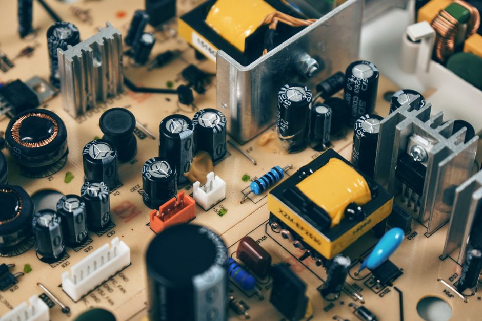
Linear power supplies typically consist of a transformer, rectifier, filter capacitor, and a pass transistor or linear regulator. One of the most frequent failure modes involves the filter capacitor. Over time, electrolytic capacitors dry out, increasing their ESR and reducing their capacitance. This leads to higher ripple and, in extreme cases, audible hum. To test a capacitor, an ESR meter provides a direct reading of its internal resistance while the capacitor remains in circuit in many cases. Comparing the measured ESR with the manufacturer’s specification or with known good values helps identify a degraded component.
Another common issue is thermal stress on the linear regulator. When the pass element dissipates significant power, the junction temperature rises, and thermal protection may cause the output to drop or cycle on and off. Measuring the regulator’s input and output voltages under load, and checking the temperature of the heatsink with a thermocouple or an infrared thermometer, can indicate whether the regulator is operating within its safe area. If the output voltage is lower than expected but the input voltage is adequate, the regulator may be in current limit or thermal shutdown. A brief reduction of the load current can confirm whether the regulator recovers. In addition, poor soldering of the regulator’s pins can introduce intermittent resistance, so visual inspection and gentle probing with a multimeter on ohms mode may reveal such defects.
Troubleshooting Switching Power Supplies
Switching power supplies are more complex than linear types, but many issues can be identified through careful observation. A common symptom is an audible whine or hiss, often caused by loose magnetic components (inductors or transformers) or by instability in the control loop. Measuring the output voltage with an oscilloscope can reveal sub‑harmonic oscillations or excessive ringing at the switching node. Probing the switching node (typically the drain of the main MOSFET) with respect to ground should show a clean square wave. If the waveform appears distorted, includes high‑frequency spikes, or shows an unusual duty cycle, further investigation into the feedback loop or snubber circuit is warranted.
Startup problems are another frequent complaint. Some switching supplies require a minimum load to regulate properly, and operating them with no load or an extremely light load can cause the output voltage to rise above the intended value or to become unstable. Adding a dummy load, such as a power resistor, can stabilize the output. Conversely, a supply that fails to start at all may have a fault in the startup resistor, the control IC, or the auxiliary winding. Measuring the voltage on the startup capacitor and the bias pin of the controller often points to the source of the problem. Since switching supplies operate at high voltages and store energy in capacitors, discharging all high‑voltage capacitors with a proper bleeder resistor before probing is essential for safety.
Using Simple Tools for Diagnosis
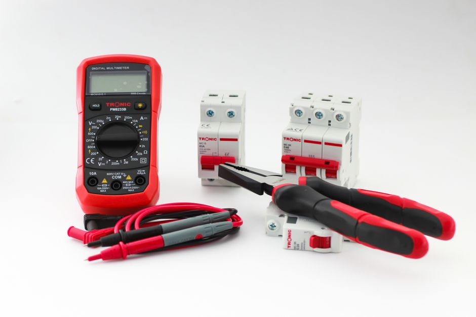
The most accessible tools for power supply troubleshooting are the digital multimeter and the oscilloscope. A multimeter provides accurate DC voltage and current readings, and its resistance mode can help trace continuity and identify short circuits. An oscilloscope, even a basic two‑channel model, reveals the shape and timing of signals that are invisible to a multimeter. For linear supplies, a multimeter alone can often detect excessive ripple if it is set to AC voltage, but the reading is an average and does not show the waveform details. For switching supplies, an oscilloscope is indispensable.
Additional instruments such as an ESR meter, a frequency counter, or a programmable load expand the diagnostic capabilities. A dummy load allows the supply to be tested under known conditions, making it easier to reproduce intermittent faults. When using any of these tools, the approach should be systematic: begin with visual inspection for swollen capacitors, burnt components, or broken solder joints; then measure voltages at key test points; and finally capture waveforms to compare with expected behavior. Documenting each measurement and noting the operating conditions helps in recognizing patterns and avoiding repeated testing. This methodical process, combined with an understanding of the circuit topology, enables technicians to isolate the majority of common power supply faults without specialized equipment.